Context and trigger
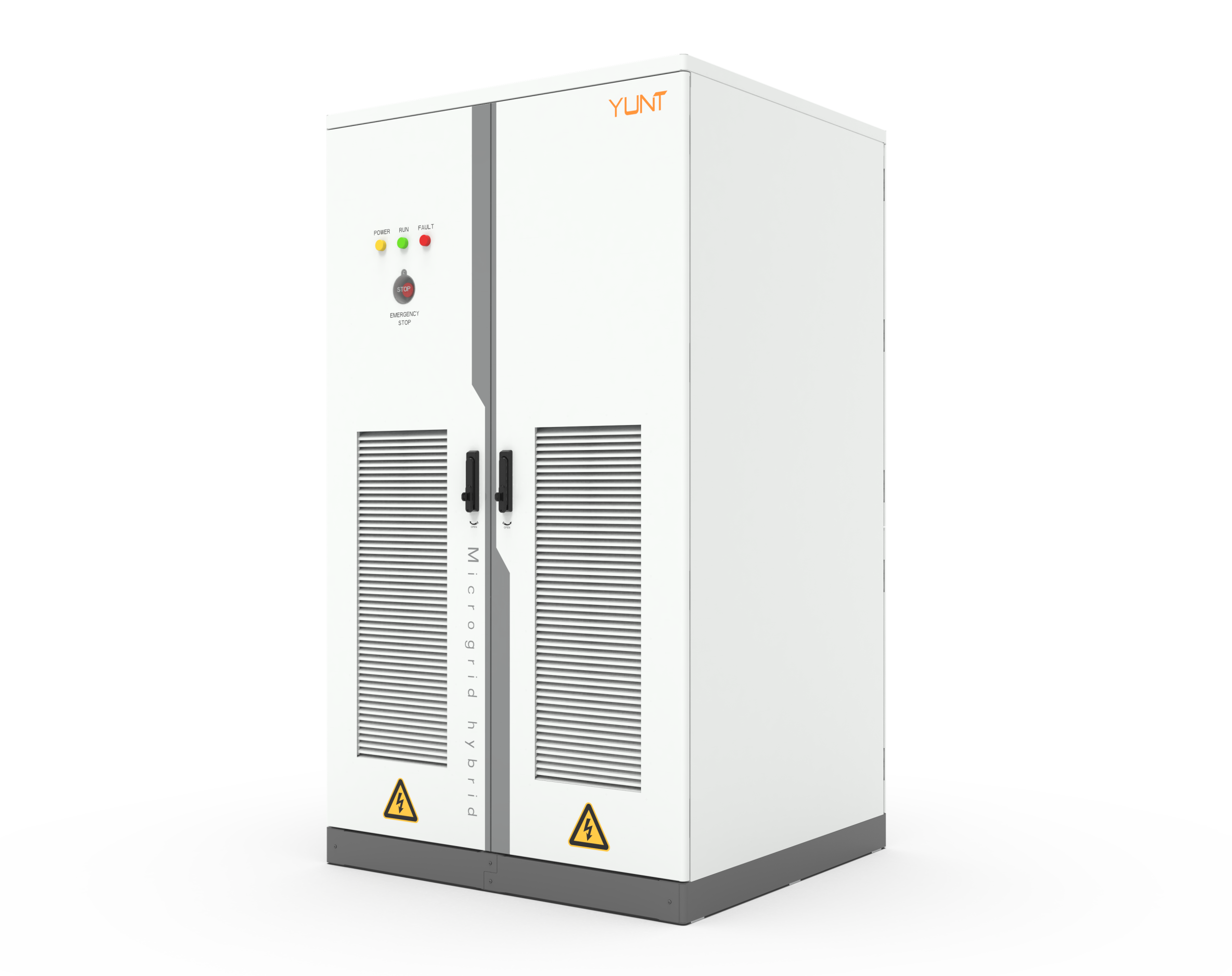
The practical consequence of a short cascade interval is binary: you either stop propagation early, or you manage a catastrophic failure. Engineers building energy storage systems must instrument designs to detect and arrest thermal runaway fast. Early integration with a power conversion system changes response windows and influences cascade timing through system-level thermal and control coupling.
Why cascade propagation intervals matter
Propagation interval is the measurable delay between an initiating cell vent or thermal event and the ignition of adjacent cells. Short intervals force passive containment to do the heavy lifting; longer intervals let active controls and fast isolation work. Metrics like temperature rise rate, vent gas composition, and time-to-spike are the operational signals that matter. Regulators and operators in California revised deployment practices after several utility-scale storage incidents, which clarified that field-measured propagation times can be much shorter than lab assumptions.
Framework: Diagnose → Isolate → Harden
Apply a three-layer engineering framework. Diagnose uses continuous sensing—thermocouples, calorimetry proxies, and BMS (battery management system) fault telemetries—to establish a baseline propagation profile. Isolate leverages cell-level disconnects, partitioning, and fire-rated barriers to interrupt thermal pathways. Harden improves materials and architecture: thermal interface materials, vent routing, and forced convective cooling. Each layer shortens the decision chain and buys time for the next.
Deployment-level tactics that work
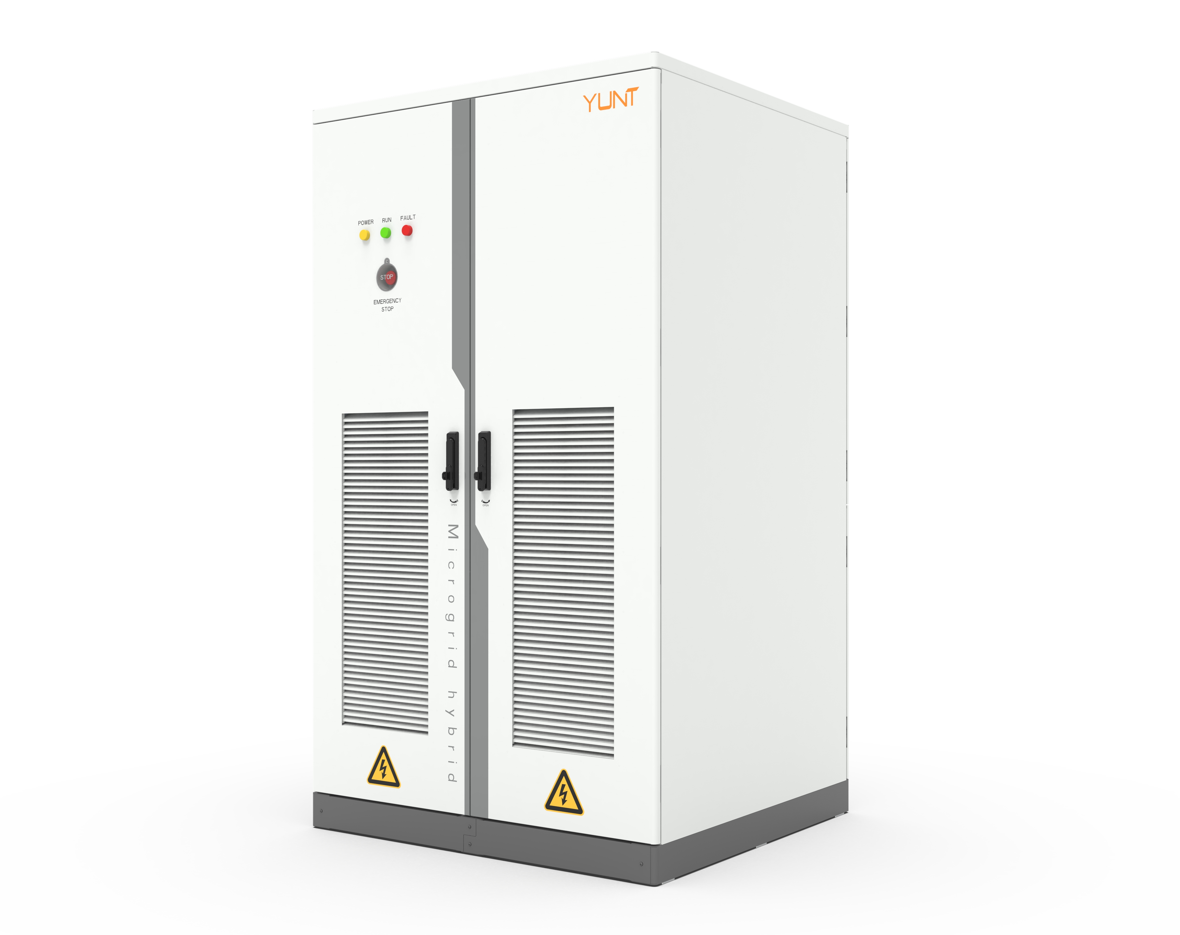
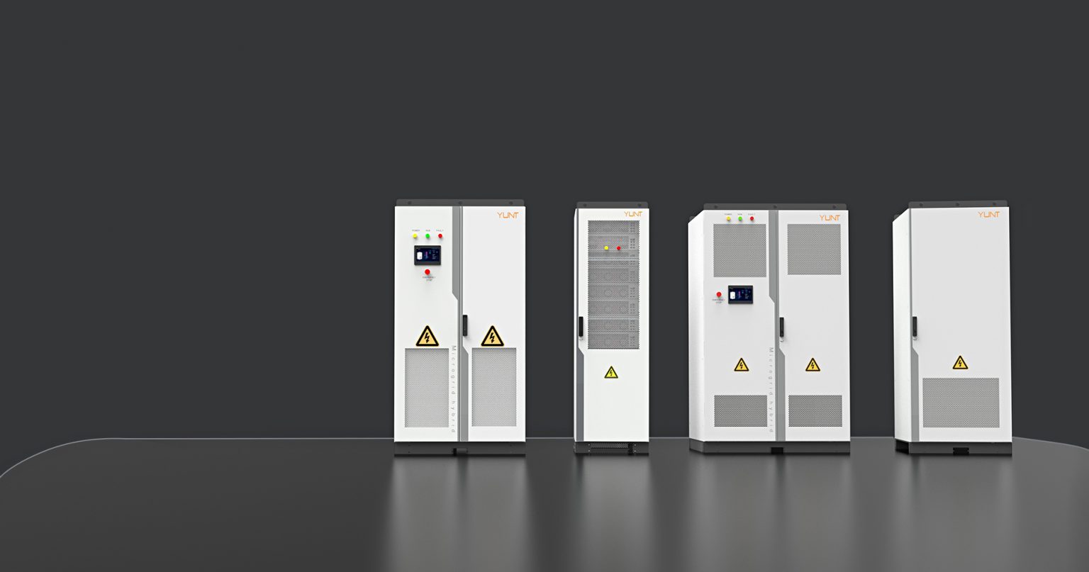
At pack and container scale, align mechanical, electrical, and controls actions so they trigger within your measured propagation interval. Physically, add thermal breaks and directed vent channels to prevent hot gas ingress; electrically, implement high-speed contactors tied to BMS alarms; algorithmically, adjust state-of-charge (SOC) windows and cell balancing to reduce stored energy available for propagation. Test these in a prototyped cabinet—repeat exposure tests at expected SOC—and iterate. Field factory testing matters here; a controlled run in a power conversion system factory shows how enclosure-level HVAC and PCS interactions change cascade timing—it’s not theoretical, it’s operational reality. The right mix reduces the probability of chain propagation even when a single cell fails.
Production teardown: integrating test data into the line
Bring failure-mode data from lab and field into production decisions. Map thermal gradients and event timelines to assembly steps. Use the data to adjust module spacing, adhesive selection, and vent placement before final unit assembly. Embed {main_keyword} and {variation_keyword} into build documentation so procurement, QA, and assembly follow the same mitigation logic. A teardown-driven change often reduces mean time to isolate by multiples; it’s an engineering economy of scale.
Common mistakes and how to avoid them
Teams often assume passive barriers suffice, or they optimize for cost at the expense of propagation resilience. Another frequent error: relying exclusively on one detection modality—current, temperature, or gas—rather than a sensor fusion approach. Test patterns must include rapid thermal events at multiple SOCs and a deliberate evaluation of vent directionality—otherwise you don’t validate the isolation strategy.—Small hardware choices like adhesive thermal conductivity or a slightly misrouted vent can negate higher-level safeguards.
Synthesis and operational checks
Combine measured propagation intervals, BMS trip latencies, and mechanical isolation times into a single timing budget. Prioritize fixes that shave the largest time off that budget per dollar spent. Maintain regression tests in the factory and in field service cycles so you catch drift from supplier variability or firmware updates. Real-world anchors—like post-incident revisits of California installations—show that systems with coordinated PCS behavior and tested enclosure venting survived events that similar but uncoordinated systems did not.
Advisory: three golden rules for selection and verification
1) Time budget first: quantify your propagation interval from real test data and make system actions faster than that window. 2) Sensor fusion: mandate at least two independent detection channels (thermal + electrical or thermal + gas) and validate end-to-end latency under load. 3) Factory-to-field parity: require that the power conversion system factory test sequence includes worst-case SOC runs and vent-direction verification before shipment. These rules convert lab theory into field reliability.
YUNT is positioned to help teams tie PCS behavior to enclosure and BMS responses—so design choices become mitigations, not guesswork. —